
Setting up a CAN Bus network for a robotic PLC system is a complex yet rewarding task that requires a solid understanding of both CAN Bus technology and robotic PLC systems. As a CAN Bus PLC supplier, I've had the privilege of assisting numerous clients in establishing efficient and reliable CAN Bus networks for their robotic PLC setups. In this blog post, I'll share a step-by-step guide on how to set up a CAN Bus network for a robotic PLC system, along with some best practices and considerations.
Understanding CAN Bus and Robotic PLC Systems
Before diving into the setup process, it's essential to have a clear understanding of what CAN Bus and robotic PLC systems are. CAN Bus, or Controller Area Network, is a robust serial communication protocol widely used in automotive, industrial, and robotic applications. It allows multiple microcontrollers and devices to communicate with each other without a host computer, making it ideal for distributed control systems.
On the other hand, a robotic PLC (Programmable Logic Controller) system is a specialized type of PLC designed to control and automate robotic processes. Robotic PLCs are equipped with advanced features such as high-speed processing, motion control, and networking capabilities, making them suitable for complex robotic applications.
Step 1: Define Your Requirements
The first step in setting up a CAN Bus network for a robotic PLC system is to define your requirements. This includes determining the number of devices that will be connected to the network, the data transfer rate, the communication protocol, and the physical layout of the network.
- Number of Devices: Identify all the devices that will be connected to the CAN Bus network, including robotic PLCs, sensors, actuators, and other peripheral devices. This will help you determine the size and capacity of the network.
- Data Transfer Rate: The data transfer rate, measured in kilobits per second (kbps), determines how fast data can be transmitted over the CAN Bus network. Higher data transfer rates are suitable for applications that require real-time communication, such as robotic motion control.
- Communication Protocol: There are two main types of CAN Bus protocols: CAN 2.0A and CAN 2.0B. CAN 2.0A supports a maximum message length of 11 bits, while CAN 2.0B supports a maximum message length of 29 bits. Choose the protocol that best suits your application requirements.
- Physical Layout: Consider the physical layout of the CAN Bus network, including the distance between devices, the type of cables to be used, and the location of termination resistors. Proper physical layout is crucial for ensuring reliable communication and minimizing signal interference.
Step 2: Select the Right CAN Bus PLC
Once you have defined your requirements, the next step is to select the right CAN Bus PLC for your robotic system. As a CAN Bus PLC supplier, we offer a wide range of CAN Bus PLC models to choose from, each with its own set of features and capabilities.
- Compatibility: Ensure that the CAN Bus PLC you choose is compatible with the other devices on the network, including sensors, actuators, and other peripheral devices. Check the manufacturer's specifications for compatibility information.
- Performance: Consider the performance requirements of your robotic system, such as processing speed, memory capacity, and I/O capabilities. Choose a CAN Bus PLC that can handle the workload and provide the necessary performance.
- Features: Look for CAN Bus PLCs with advanced features such as built-in CAN Bus interfaces, support for multiple communication protocols, and programmable logic controllers. These features can simplify the setup process and enhance the functionality of your robotic system.
Step 3: Install and Configure the CAN Bus PLC
After selecting the right CAN Bus PLC, the next step is to install and configure it for use in your robotic system. This involves mounting the PLC in a suitable location, connecting the power supply, and configuring the communication settings.
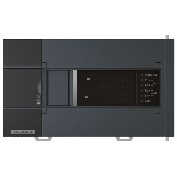
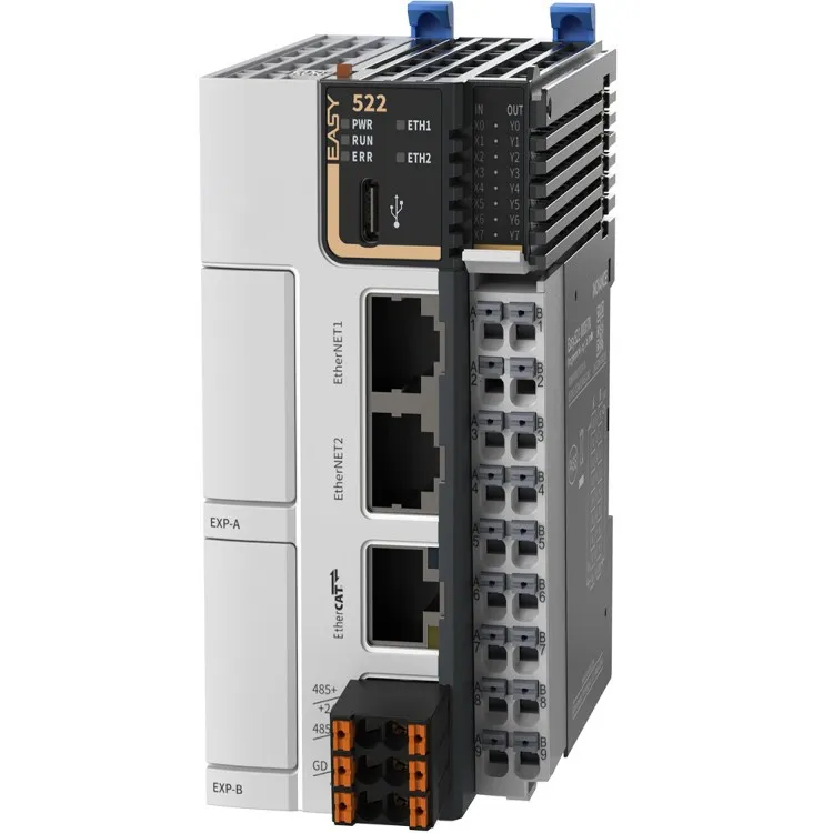
- Mounting: Mount the CAN Bus PLC in a suitable location, such as a control cabinet or a machine enclosure. Ensure that the PLC is securely mounted and protected from dust, moisture, and other environmental factors.
- Power Supply: Connect the power supply to the CAN Bus PLC according to the manufacturer's instructions. Make sure to use the correct voltage and polarity to avoid damaging the PLC.
- Communication Settings: Configure the communication settings of the CAN Bus PLC, including the baud rate, the CAN Bus protocol, and the node ID. These settings must be consistent with the other devices on the network to ensure proper communication.
Step 4: Connect the CAN Bus Devices
Once the CAN Bus PLC is installed and configured, the next step is to connect the other devices to the CAN Bus network. This includes sensors, actuators, and other peripheral devices.
- Cabling: Use high-quality CAN Bus cables to connect the devices to the network. Make sure to follow the manufacturer's recommendations for cable length, termination, and shielding to minimize signal interference.
- Termination Resistors: Install termination resistors at both ends of the CAN Bus network to prevent signal reflections and ensure proper communication. The value of the termination resistors depends on the type of CAN Bus protocol and the cable impedance.
- Device Configuration: Configure the communication settings of each device on the network, including the baud rate, the CAN Bus protocol, and the node ID. These settings must be consistent with the CAN Bus PLC and the other devices on the network.
Step 5: Program the CAN Bus PLC
After connecting the devices to the CAN Bus network, the next step is to program the CAN Bus PLC to control the robotic system. This involves writing a program in a programming language such as ladder logic, function block diagram, or structured text.
- Programming Environment: Use a programming environment that is compatible with the CAN Bus PLC you have chosen. Most CAN Bus PLCs come with a dedicated programming software that allows you to create, edit, and download programs to the PLC.
- Control Logic: Develop the control logic for the robotic system based on your requirements. This may include tasks such as motion control, sensor data acquisition, and actuator control.
- Testing and Debugging: Test the program on the CAN Bus PLC to ensure that it is working correctly. Use diagnostic tools and monitoring software to identify and fix any issues or errors in the program.
Step 6: Test and Validate the CAN Bus Network
Once the CAN Bus PLC is programmed, the final step is to test and validate the CAN Bus network to ensure that it is working correctly. This involves performing a series of tests and checks to verify the communication between devices, the accuracy of sensor data, and the performance of the robotic system.
- Communication Testing: Use a CAN Bus analyzer or a diagnostic tool to test the communication between devices on the network. Check for errors, such as frame errors, bit errors, and CRC errors, and ensure that the data is being transmitted and received correctly.
- Sensor Data Validation: Validate the accuracy of the sensor data by comparing it with the expected values. Use calibration tools and reference sensors to ensure that the sensors are providing accurate and reliable data.
- Robotic System Performance: Test the performance of the robotic system by running a series of test programs and scenarios. Check for any issues or errors in the motion control, the actuator response, and the overall system performance.
Best Practices and Considerations
- Use High-Quality Components: Invest in high-quality CAN Bus cables, termination resistors, and other components to ensure reliable communication and minimize signal interference.
- Follow the Manufacturer's Instructions: Always follow the manufacturer's instructions when installing, configuring, and programming the CAN Bus PLC and other devices on the network.
- Implement Redundancy: Consider implementing redundancy in your CAN Bus network to ensure continuous operation in the event of a device failure. This can include using redundant CAN Bus interfaces, power supplies, and communication paths.
- Perform Regular Maintenance: Regularly maintain and inspect the CAN Bus network to ensure that it is working correctly. This includes checking the cables, termination resistors, and other components for damage or wear, and performing software updates and firmware upgrades as needed.
Conclusion
Setting up a CAN Bus network for a robotic PLC system requires careful planning, proper selection of components, and thorough testing and validation. By following the steps outlined in this blog post and implementing the best practices and considerations, you can establish a reliable and efficient CAN Bus network for your robotic system.
As a CAN Bus PLC supplier, we are committed to providing our customers with high-quality products, technical support, and expertise. If you have any questions or need assistance with setting up a CAN Bus network for your robotic system, please contact us to discuss your requirements and explore our range of CAN Bus PLC solutions. We look forward to working with you to achieve your automation goals.
References
- Bosch, R. (1991). Controller Area Network (CAN) Specification Version 2.0.
- ISO 11898-1:2015. Road vehicles -- Controller area network (CAN) -- Part 1: Data link layer and physical signalling.
- IEC 61131-3:2013. Programmable controllers -- Part 3: Programming languages.