
As a CAN Bus PLC supplier, I've encountered numerous inquiries regarding the installation requirements for CAN Bus in a PLC cabinet. In this blog, I'll delve into the essential aspects of installing CAN Bus in a PLC cabinet, providing valuable insights and guidelines to ensure a smooth and efficient installation process.
Understanding CAN Bus
CAN (Controller Area Network) Bus is a robust serial communication protocol widely used in industrial automation, automotive, and other applications. It allows multiple nodes (such as sensors, actuators, and controllers) to communicate with each other over a single bus, providing a reliable and cost - effective solution for data exchange.
CAN Bus offers several advantages, including high data transfer rates, excellent noise immunity, and the ability to support multiple nodes on the same network. In a PLC cabinet, CAN Bus can be used to connect various input and output modules, as well as other devices, enabling seamless integration and control.
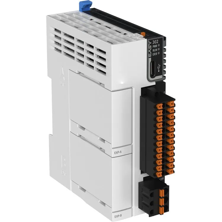
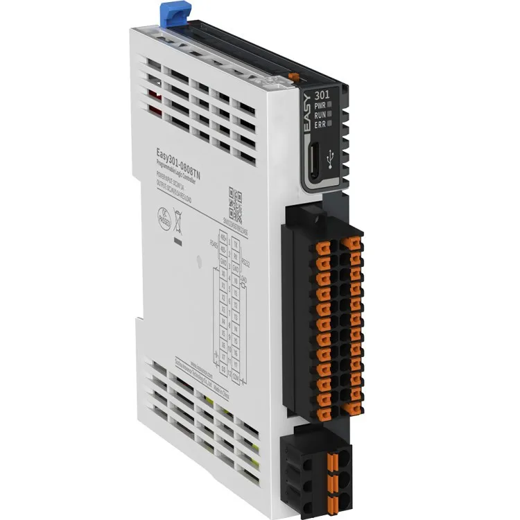
Physical Installation Requirements
Cable Selection
The choice of cable is crucial for the proper functioning of the CAN Bus. A high - quality shielded twisted - pair cable is recommended to minimize electromagnetic interference (EMI) and radio frequency interference (RFI). The cable should have a characteristic impedance of 120 ohms, which is the standard impedance for CAN Bus networks.
The cable length is also an important consideration. Longer cables can introduce signal attenuation and delay, which may affect the performance of the CAN Bus. As a general rule, the maximum cable length for a CAN Bus network is around 40 meters at a bit rate of 1 Mbps. If longer distances are required, repeaters or line drivers can be used to boost the signal.
Termination
Proper termination is essential for a CAN Bus network. Each end of the bus must be terminated with a 120 - ohm resistor to prevent signal reflections. These resistors should be connected between the CAN_H and CAN_L lines at the two ends of the bus.
In a PLC cabinet, the termination resistors can be integrated into the CAN Bus interface modules or added externally. It's important to ensure that the termination resistors are correctly installed and that there are no open or short circuits in the termination network.
Grounding
Good grounding is necessary to reduce electrical noise and interference in the CAN Bus network. The PLC cabinet should be properly grounded, and all CAN Bus devices should be connected to a common ground. This helps to equalize the electrical potential between different devices and minimize the risk of ground loops.
It's also important to avoid using long ground wires, as they can act as antennas and pick up electromagnetic interference. Instead, use short and direct ground connections to ensure a low - impedance path to ground.
Electrical Requirements
Power Supply
CAN Bus devices typically require a stable power supply. In a PLC cabinet, the power supply should be able to provide sufficient voltage and current to all the connected CAN Bus devices. It's important to check the power requirements of each device and ensure that the power supply has enough capacity to meet the total load.
In addition, the power supply should be well - regulated to prevent voltage fluctuations, which can affect the performance of the CAN Bus. A voltage regulator or a UPS (Uninterruptible Power Supply) can be used to provide a stable power source.
Signal Isolation
Signal isolation is often required in a CAN Bus network to protect the devices from electrical noise and interference. Isolation can be achieved using opto - isolators or transformers. These devices separate the electrical circuits of different nodes, preventing the transfer of electrical noise and interference between them.
In a PLC cabinet, signal isolation can be integrated into the CAN Bus interface modules or added externally. It's important to ensure that the isolation devices have a high isolation voltage rating and a low coupling capacitance to provide effective isolation.
Environmental Requirements
Temperature and Humidity
The PLC cabinet should be installed in an environment with suitable temperature and humidity conditions. CAN Bus devices are typically designed to operate within a certain temperature range, usually between - 40°C and 85°C. High temperatures can cause the components to overheat and fail, while low temperatures can affect the performance of the electronic circuits.
Similarly, high humidity can cause corrosion and short - circuits in the electrical components. The humidity level in the PLC cabinet should be kept within the recommended range, usually between 10% and 95% relative humidity.
Dust and Vibration
The PLC cabinet should be protected from dust and vibration. Dust can accumulate on the electrical components and cause short - circuits or overheating. Vibration can also loosen the connections and damage the components.
To protect the PLC cabinet from dust, it can be installed in a sealed enclosure or equipped with air filters. To reduce the effects of vibration, the cabinet can be mounted on shock - absorbing mounts or isolators.
Network Configuration
Node Addressing
Each CAN Bus device on the network must have a unique node address. This address is used to identify the device and enable communication between different nodes. The node addresses can be set manually or assigned automatically using a configuration tool.
In a PLC cabinet, the node addresses of the CAN Bus devices should be carefully planned to ensure that there are no address conflicts. The addressing scheme should also be documented for future reference.
Bit Rate Selection
The bit rate of the CAN Bus network determines the speed at which data can be transmitted. The bit rate can be selected based on the requirements of the application. Higher bit rates allow for faster data transfer, but they also reduce the maximum cable length and increase the susceptibility to interference.
Common bit rates for CAN Bus networks include 125 kbps, 250 kbps, 500 kbps, and 1 Mbps. When selecting the bit rate, it's important to consider the cable length, the number of nodes on the network, and the type of data being transmitted.
Installation in a PLC Cabinet
Mounting the CAN Bus Modules
The CAN Bus modules should be mounted securely in the PLC cabinet. They should be installed in a location that allows easy access for maintenance and troubleshooting. The modules should also be arranged in a way that minimizes the cable length between different devices and reduces the risk of cable interference.
Cable Management
Proper cable management is essential in a PLC cabinet. The CAN Bus cables should be neatly organized and routed to avoid crossing or tangling with other cables. Cable ties or cable trays can be used to secure the cables and keep them in place.
It's also important to label the cables clearly to identify their function and destination. This makes it easier to troubleshoot the CAN Bus network and perform maintenance tasks.
Conclusion
Installing a CAN Bus network in a PLC cabinet requires careful planning and attention to detail. By following the installation requirements outlined in this blog, you can ensure a reliable and efficient CAN Bus network that meets the needs of your application.
If you're interested in Compact Mini PLC, CAN Bus PLC, or EtherCAT Bus PLC, or if you have any questions about the installation of CAN Bus in a PLC cabinet, please don't hesitate to contact us for further information and to discuss your procurement needs.
References
- ISO 11898-1:2015, Road vehicles -- Controller area network (CAN) -- Part 1: Data link layer and physical signalling
- Bosch CAN Handbook, Robert Bosch GmbH